My current homelab consists of three Armsom Sige7 nodes. Having multiple identical boards allows me to experiment with different configurations, test deployment strategies, and simulate small-scale distributed environments.
What makes the Armsom Sige7 especially interesting is that it’s open-source hardware. This gives me full visibility into the board layout, which opens the door to deeper hardware-level integrations that are normally difficult—or impossible—on closed systems.
Building an Out-of-Band Management Plane for My Homelab
The main goal of this project is to build a lightweight management plane for the Sige7 nodes—something similar in spirit to IPMI or BMC functionality found in enterprise servers, but tailored for a DIY homelab.
Specifically, I want to:
- Access the serial console out-of-band
- Remotely shut down the device
- Power it on remotely
- Push new OS images without manual intervention
With these capabilities in place, I can fully automate provisioning and management of the entire homelab. Re-imaging all nodes or recovering a failed system becomes a matter of running a script instead of physically interacting with each board.
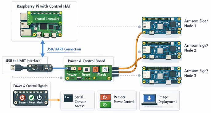
Architecture Overview
At the center of the setup is a Raspberry Pi acting as the management controller.
This Raspberry Pi connects to each Sige7 node in two ways:
- USB connections – used for serial communication and image flashing
- GPIO (Input/Output) – used to control power and button signals
This effectively turns the Raspberry Pi into a custom-built out-of-band management system.
Hardware Integration
One of the key advantages of the Sige7 is its compatibility with the standard 40-pin header layout used by the Raspberry Pi. This makes integration much simpler.
Using this 40-pin interface, I can:
- Access the UART for serial console communication
- Provide power to the board
- Interface with control signals like reset and boot mode
To organize everything cleanly, I designed a breakout board.
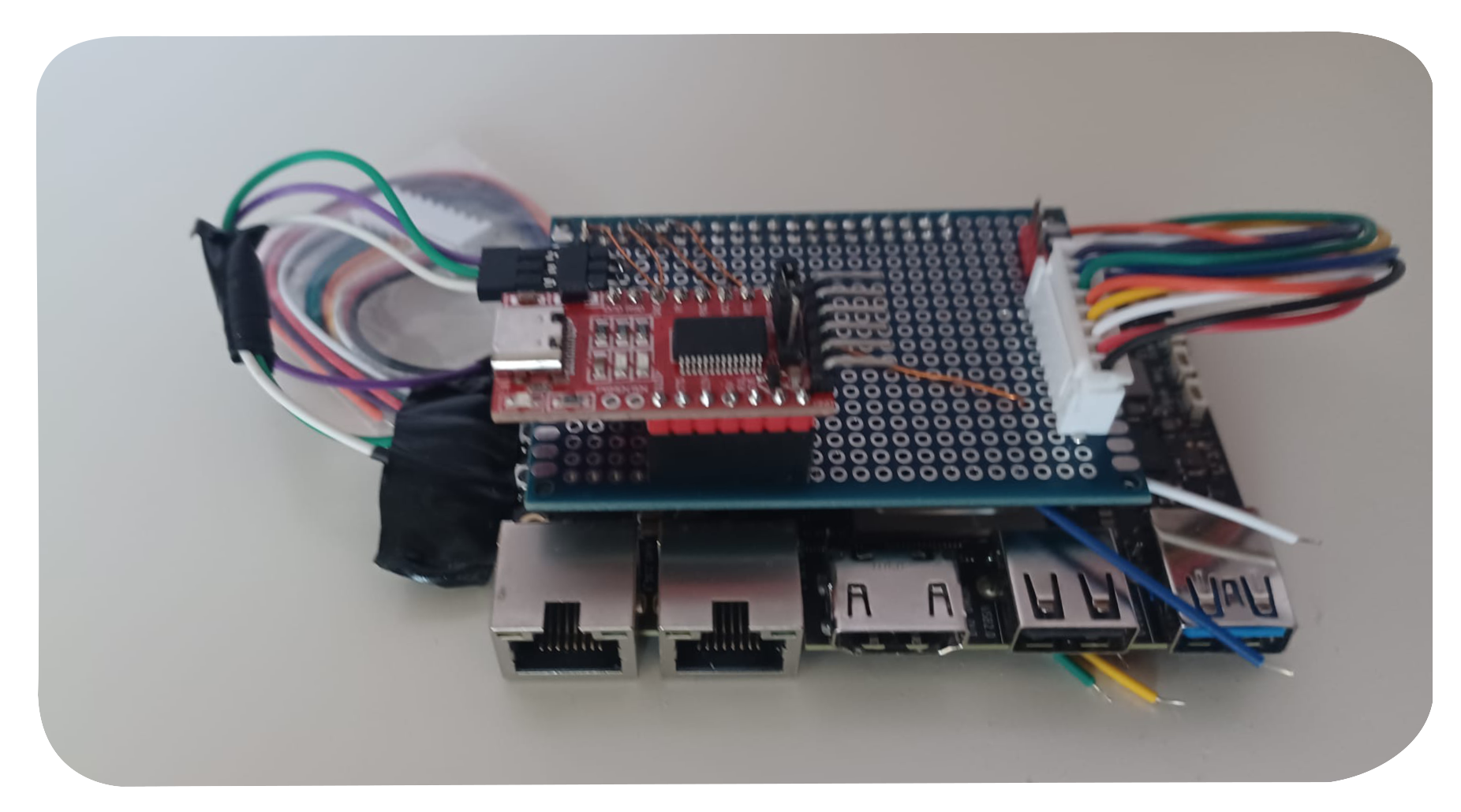
Breakout Board Design
The breakout board serves multiple purposes:
- Exposes the UART console via a dedicated connector
- Supplies power to the Sige7
- Breaks out connections for:
- Power button
- Reset button
- Flash (boot mode) button
The UART lines are routed to a connector that interfaces with a USB-to-UART adapter. This allows the Raspberry Pi to communicate with each node over USB, making serial access fully scriptable.
Meanwhile, the power and control signals (power, reset, flash) are bundled into a cable and routed to a central control PCB. This PCB connects back to the Raspberry Pi’s GPIO pins, enabling software control over physical actions.
What This Enables
With this setup, I now have:
- Full serial access to each node without plugging in cables manually
- The ability to simulate button presses programmatically
- Remote power control for each device
- A path toward fully automated image deployment
In essence, I’ve built a small-scale, custom out-of-band management system tailored specifically for my homelab.
What’s Next
With the design in place, I’m now moving into the first tangible phase: building and testing the initial boards. This stage is all about validating assumptions—making sure the wiring, signal routing, and control mechanisms behave exactly as expected in practice.
Once the prototypes are proven, the next step is to evolve the design into something more structured and reusable:
- Design a dedicated PCB as a Raspberry Pi HAT for each Sige7 node
- Develop a central controller HAT that aggregates control over multiple nodes
- Write the software layer that orchestrates communication, power control, and image deployment
The software will ultimately tie everything together—handling serial connections, triggering GPIO actions, and automating the provisioning workflow. The goal is to make interacting with the entire homelab feel as simple as managing a single system.
If all goes as planned, this will transform the setup from a collection of development boards into a cohesive, remotely managed infrastructure.
Comments
You can respond to this post on Mastodon: 🔗 or click to copy the URL to your clipboard so you can paste it into your client.